Platform on civil engineering, underground infrastructure, energy, construction equipment & construction machinery

Consortium De Groene Boog, which includes the companies Besix, Dura Vermeer, Van Oord, TBI (Mobilis, Croonwolter&dros), Rebel and John Laing, is realizing project A16 Rotterdam on behalf of Rijkswaterstaat. The new A16 Rotterdam will be an 11 kilometer long national highway between the A16/A20 at Terbregseplein and the A13 at Rotterdam The Hague Airport.
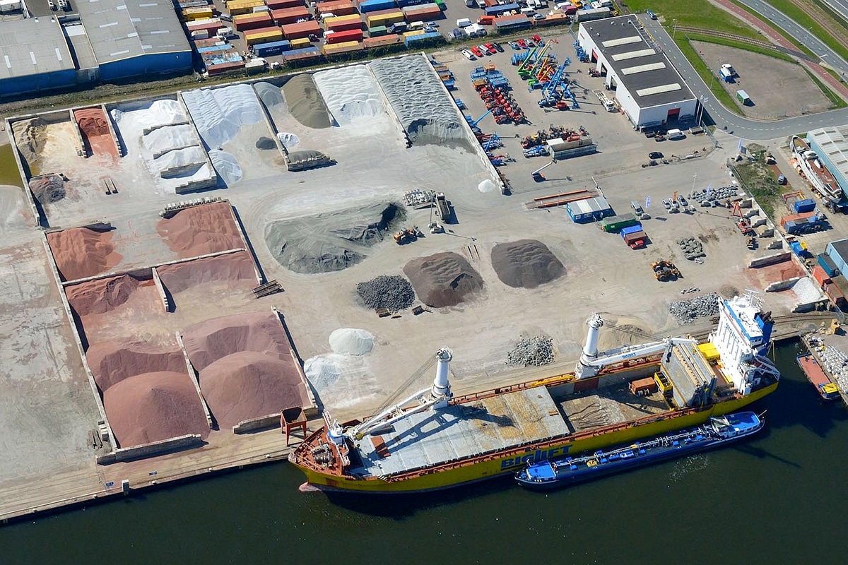
Part of the 11-kilometer route is the newly constructed Rottemer Tunnel, with a length of 2.2 km (3.0 km including ramps). A special project, because the choice was made to work in the wet. Underwater concrete will be used, which will be poured by diving teams. GWW Magazine visited the construction site and talked to Kenneth Wyns, design manager tunnel, Wim Guis, project manager tunnel and Sander Tetteroo, head civil engineer tunnel.

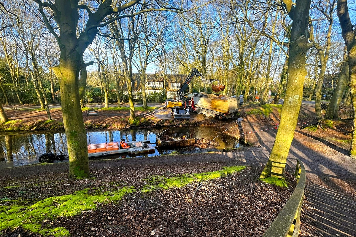
"Reinforced underwater concrete is used more often, however, this is the first time it has been done on such a scale, in this case 2.2 km," says Guis. "The advantage is that less concrete is needed, which results in a low MKI value. That does mean that all the work has to be done under water: the excavation, the cleaning of the foundation pile heads -a whopping 7,700 of them, the placement of the expansion joint beams, each weighing 90 tons, the placement of the reinforcement and the concrete pour itself. On peak days, 35 to 40 diving teams are therefore active." The Rottemer Tunnel is thus a special subproject in every respect, running right through the Lage Bergse Bos near Rotterdam, divided into 34 construction pits ranging from 50 to 200 meters.

Wyns explains how this design was arrived at: "While maintaining quality, we wanted to arrive at the most appropriate MKI value in DuboCalc. The guiding question was: what can we do with less material? What would be the most sustainable design? The calculations made revealed that there was a "vertical equilibrium. The upward force on the floor in the temporary phase was of the same order of magnitude as the downward ground pressure in the final phase, so we could work with one pile length. Economically, this was ideal. By choosing reinforced underwater concrete, fewer piles could be used. Would you have chosen unreinforced concrete in this case, a pattern with piles every 3.5m or so would have been required. Now in the cross-section of the tunnel it is sufficient to have 2 piles under the outer walls and 2 piles under the middle tunnel channel. So in the cross-section you see only 6 piles. This is not only a significant material reduction, but also means less work. Important factors that affect the MKI."
The design emerged during the tender phase. Wyns: "The tunnel has a geotechnical longitudinal profile over 2.2 km, from ground level at -6 meters NAP to -15/-20 meters NAP, consisting of layers of clay and peat. The composition does vary within that 2.2 km distance. The sand layer is up to 2-3 meters below the concrete floor. In the soft layer, there is 4 to 5 meters difference in thickness. Design-wise, it was optimal to calculate a cut every 25 meters according to the determined soil profile. This way, the required reinforcement could be determined and the number of piles could be calculated for that cut. By calculating parametrically, we were able to arrive at 5 different reinforcement configurations for the floor. The advantage of parametric design is that if something changes somewhere, the change is also implemented at other locations. That saves a lot of engineering hours." Tetteroo adds, "The design really had to be 'hufter proof,' taking into account the needs of the design and the needs in execution. For that, there was a lot of consultation with between the design department and the execution team."

"One feature of a submerged concrete floor is that there are many tolerances in terms of flatness," explains Guis. "The formwork for the walls had to be made suitable for this: for example, this custom-made formwork has hydraulically adjustable panels so that a good connection can be made from the wall to the floor. A mockup was made of the tunnel's reinforced underwater concrete floor, so that it could be practiced in the dry. A lot of time and energy went into the tolerance analysis, and the design was geometrically put into a "roomy design. So therein lies the challenge: how do you 'knot' everything together within those tolerances?"
Tetteroo adds: "In this design process, BCS, the supplier of the reinforcing steel, was also heavily involved. In consultation, they drew the entire reinforcement structure in 3D. A lot of attention was paid to the details at the front, because we can't afford any mistakes when working underwater." Wyns: "The design went through three reviews; the municipality, Rijkswaterstaat and SecoNed looked on during the design phase."
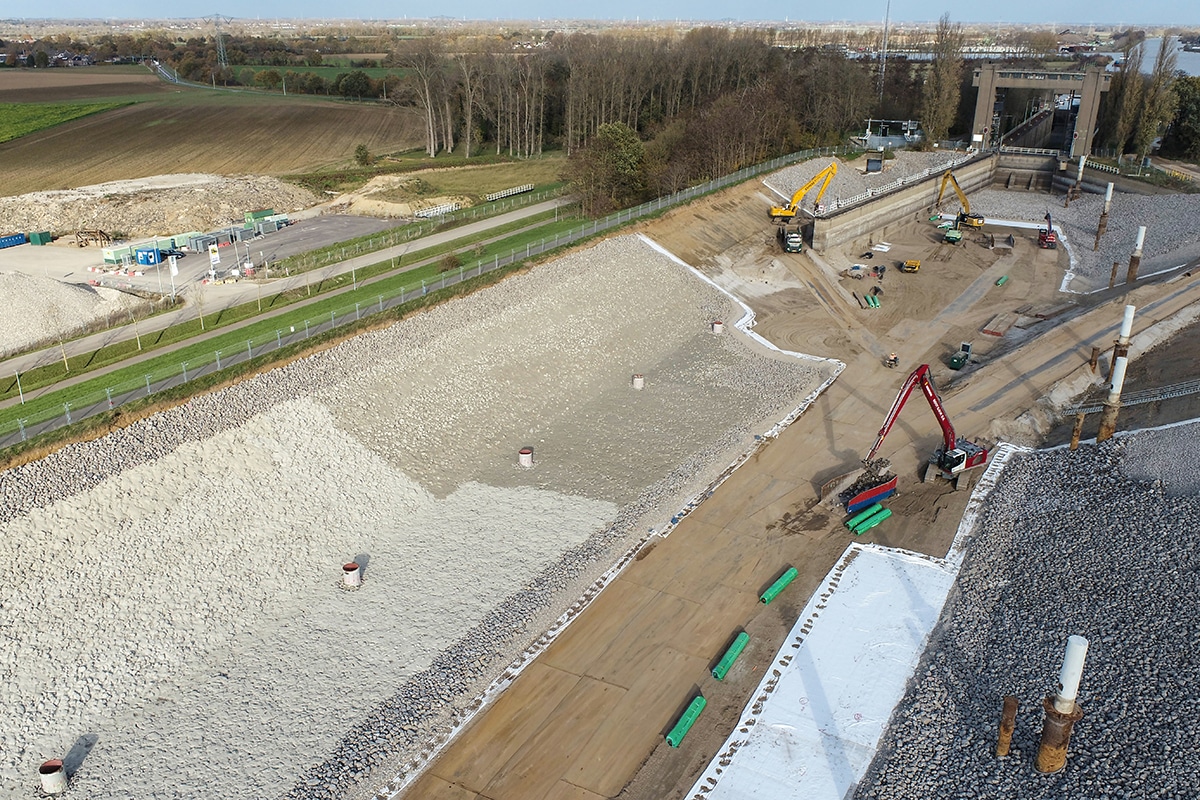
After the excavation, gravel application and installation of the relief tubes, the piles are cleaned. Guis: "After that, horizontal piles are installed, these lie on the gravel. These ensure that the reinforcement does not touch the gravel and that there is sufficient concrete cover on the underside of the structure. On top of this, the first and second layers of reinforcement are laid. This reinforcement is delivered prefabricated. Then the dishes are applied, with nut, to absorb the tensile force in the floor and discharge it to the concrete piles. Over the piles come reinforcement baskets, which are matched to the tolerances of installing the piles. This allows the basket to be placed over the pile without having to grind or adjust the reinforcement. Being able to play with the layers allows us to apply the suspension reinforcement properly. Then two more layers of top mesh follow, after which the concrete pour can begin." Tetteroo adds: "Also special is a tool developed together with HYTORC that allows us to lengthen the GEWI rod under water and set it to moment."
At the time of this writing, 6 tubs have now been poured and drained, out of 34 tubs. Guis: "We are working in order, sort of a train. We expect to have poured 3 more tubs before Christmas."
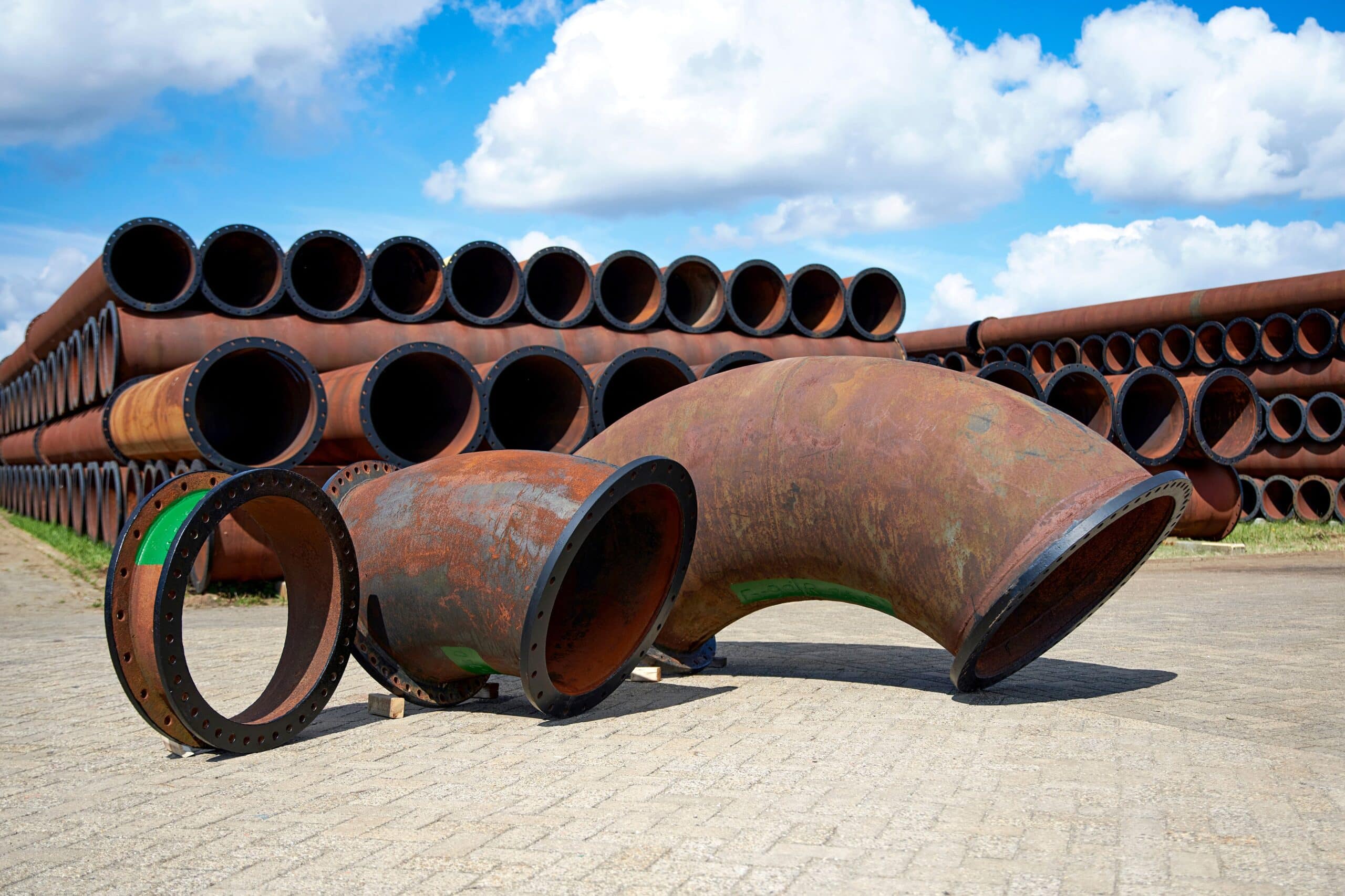
Normally, a dilatation profile would be installed in the dry between the tunnel segments. Tetteroo: "In the tender it was decided to make prefabricated dilatation beams alongside the construction pit and position them in the wet. Underwater concrete is then poured against them on both sides, alternating in 20-cm increments, to prevent the beam from tilting. The making, transporting and hoisting is completely fine-tuned and really special. A dilatation beam itself weighs 76 tons (!) and with lifting frame the combination weighs 90 tons. A beam is therefore lifted with 3 cranes. The lifting and transport frame was developed in cooperation with Sarens. They provided excellent input at the front end of the process. Without the right partners you don't make it, with this kind of project." Wyns emphasizes, "Companies like Sarens, BCS and Dyckerhoff Basal (concrete) are important in the design phase, we get the right information from them and can use them as a sounding board."

Tetteroo says of the formwork, "The formwork was designed specifically for this tunnel, with a lot of consultation between Kenneth's design team, Hendriks Precon and BCS. Everything had to be able to be braided ahead, so that on site the reinforcement had to be adjusted as little as possible. The design team looked at all reinforcement variants with BCS to come up with a short list. A choice was finally made. To cope with the tolerances of the (erratic) top side of the underwater concrete, we designed a system with Hendriks to quickly seal the voids between the bottom of the formwork and the top side of the concrete floor. The solution was found in a system of panels of 1.5 meters, equipped with self-adjusting hydraulics. At the push of a button, you can cover 15 cm height difference."
As with the other two subareas of The Green Bow, subarea 2, the tunnel, is a learning project. Says Wyns, "We continue to strive for innovative designs using as little material as possible. This project has taught us many lessons. With the requirement from the Department of Public Works that the groundwater level should not be affected and the resulting choice for a closed construction pit with a reinforced underwater concrete floor came the challenges, which we were able to successfully overcome. This is the kind of project that acts as a benchmark for future sustainable designs."