Platform on civil engineering, underground infrastructure, energy, construction equipment & construction machinery

Two giant identical bascule bridges are part of the New Terneuzen Lock project. As part of a large integrated design team, Iv-Infra produced the design for the bascule bridges, steel rolling gates and level gates of the new lock.
This article explains the design of the bascule bridges. The two bascule bridges are located in the New Lock at the lock heads, still outside the steel lock doors (roller type doors). There is a bridge over each lock head to allow road traffic to pass over the lock at all times.
Typically, movable bridges are kept closed during approaching storms to prevent the bridge from being subjected to the enormous wind loads in the open position. The bascule bridges over the new lock, however, are capable of withstanding these wind loads: in the event of an approaching storm that may be accompanied by a storm surge, the bridges will instead be opened and locked in the open position to prevent the bridges from being severely damaged by the storm surge, which is expected to exert much higher loads on the bridge than the wind load in the open position. In such a situation, where the bridge protrudes about 70 meters above the water level, the wind load on the upper segment of the opened bridge deck exceeds 2.3 kN/m2.
Both bascule bridges are almost identically constructed and consist of a fully welded, steel movable section (trap), composed of: a deck plate, finished with an epoxy wear layer and stiffened with trough-shaped stiffening profiles along the direction of the bridge; 19 transverse girders, center-to-center 3.10 meters; 2 main girders with trusses, center-to-center 9.40 meters, not coupled to each other; a ballast box with ballast, suspended at the end of the trusses.
The cross girders connect to the lower edge of the main girders, and the cross girders under the bicycle/footpaths rejuvenate in height to the bridge edges. The driving deck for motorized traffic is located between both truss girders, which are protected from collision by vehicles with half step barriers. On the outside of the main girders are the bicycle/footpaths. The total width of the bridge is 17.25 m.
At the location of the bridge basement, the main girders protrude into two elongated slots in the basement deck of the bridge basement, the ballast box is located in the bridge basement directly under the basement deck.
To span the 55-meter-wide gully and provide space for the hydraulic drive cylinders, which are positioned forward of the pivot point, the bridges have been given a total span of 65.85 meters, measured from pivot point to center of front spans.
The total length of the bridges is 85.65 meters and the total mass about 2,200 tons per bridge (steel structure + ballast). This puts the bridges in line with the largest bascule bridges in Europe.
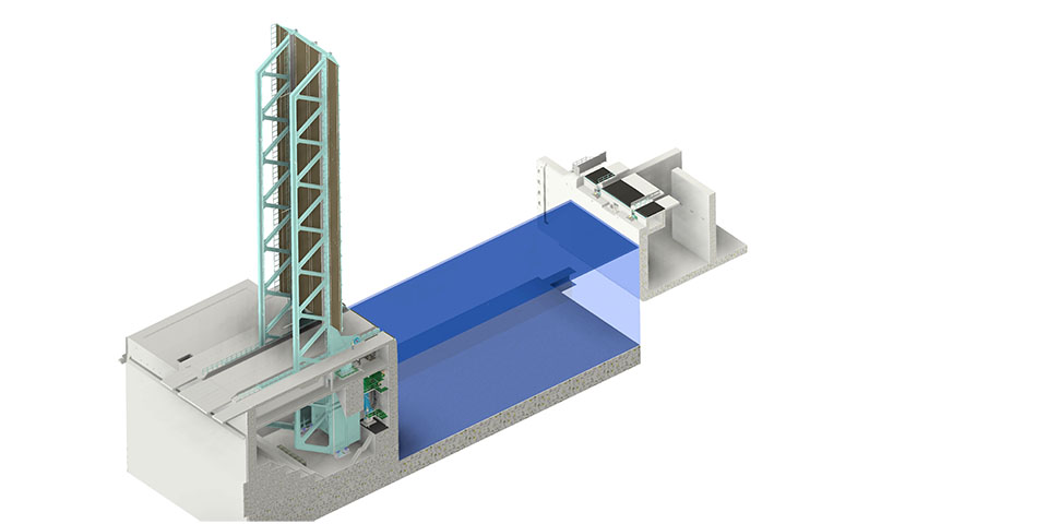
Overview bridge opened.
The bridge is balanced around the pivot point with a (prescribed) closing moment of 3300 kNm in the closed position and an opening moment in the fully open position (90°) of 1900 kNm.
The ballast box behind the pivot point of the bridge is positioned and filled with ballast so that this balance can be achieved precisely. The ballast box is constructed of thick stiffened steel plate and filled with fixed ballast and so-called control ballast (removable ballast). The fixed ballast (about 920 tons) consists of a combination of steel billets and concrete, weighted with magnadense. The control ballast (about 90 tons) is intended for fine-tuning the balance and for future adjustment and consists of steel "rolls" of about 20 kg/piece. In addition, there is empty space in the ballast box available to accommodate additional control ballast in the future.
The mechanical equipment consists of all the mechanical devices and components designed to enable the opening, closing and locking of the movable bridge. In this case: 4 main pivot points equipped with spherical roller bearings, on which the bridge rotates about a horizontal axis; the bridge drive: 2 hydraulic cylinders that collectively open and close the bridge; the locking in closed position: the 2 latches at the front of the trap, which lock the bridge in closed position and secure the fixed position of the bridge when it is traversed by road traffic; the locking in open position: the latch in the bridge basement on the basement floor that locks the bridge in the open position (90˚) at each bridge opening and ensures safe passage of shipping traffic; a centering device: a device on the front of the bridge that centers the bridge when closed and fixes it transversely in the closed position in relation to the embankment abutment, ensuring safe passage of road traffic.
The trap is equipped with two pieces of forged steel shafts, each inserted through a thickened part of the web plate in the main beam. On the studs of the shafts are bearings, housed in steel bearing housings. The bearing housings are mounted via steel lower seats on a concrete platform at the front wall of the bridge basement. A reliable and robust type of roller bearing was chosen for the main bearings: a double-row barrel bearing. This type of bearing is self-aligning: it can accommodate small misalignments of the shaft without generating relevant bending moments on the shaft. In addition, the bearing has a very low rolling resistance. The cast steel bearing housings are designed with a horizontal division, in the center of the rotation axis.
The bridge drive consists of two substantial parallel, double-acting hydraulic cylinders with bottom eye and rod clevis, driven by a hydraulic unit, positioned centrally between both cylinders on the concrete platform on which the main pivot points are also supported. The cylinders are each placed in the center of a main girder, between the main pivot point and the column wall/cellar front wall. The bottom hinge is incorporated into a steel seat on a concrete console at the front wall of the bridge cellar. The rod clevis is connected to an eye under the main girder of the bridge structure. The movements of the bridge are controlled on the basis of a predetermined speed diagram, programmed in a so-called control chart.
The centering device consists of a solid centering roller at the center of the bridge, attached to the underside of the front cross member of the trap. When the bridge is closed, the centering roller runs in a catch assembly mounted on an indentation in the overlay head. The roller is supported on a forged steel shaft with fiber-reinforced plastic sliding sleeve, to avoid large frictional forces between the steel roller and catch structure and to minimize wear of the centering device, thus ensuring a long service life.