Platform on civil engineering, underground infrastructure, energy, construction equipment & construction machinery

The renewal of the Beatrix Bridge and the Kogerpolder Bridge is part of the Province of North Holland's 'N244-N246 Trajectory Approach' project. In the process, the Beatrix Bridge has also been renamed the Princess Amalia Bridge, the first of the two bascule bridges to be replaced and put into service (early) in 2019. The Kogerpolder Bridge was also put into service early this year.
One of the main wishes in replacing the Princess Amalia Bridge and the Kogerpolder Bridge was to minimize maintenance. In addition, Province of North Holland stated that the alignment should not be changed. This meant that both bridges had to be built in the same location as the existing bridges and the alignment of the road could not be changed. Minimizing disruption and thereby reducing and shortening on-site construction activities as much as possible was also a determining factor in the design of the bridges.
The bridges are composed of two approach bridges, a bascule basement and a steel trap. The Princess Amalia Bridge has two lanes of traffic and a separate bicycle path. The Kogerpolder Bridge has three lanes of traffic and a separate bicycle path. The architectural design of both bridges is similar in many areas, so that both bridges clearly belong to one family in accordance with the image quality plan. By opting for a tapered bridge deck and pointed ends of piers, a slimmer appearance has been created.

The existing bridges were completely demolished. Only the existing pile foundation was not removed, but remained in the ground. Because the new bridges are in exactly the same position as the existing bridges, designing the new piles was quite a puzzle. Archival records and as-built drawings were used to visualize the existing pile plan. The new pile plan was designed around this and included in a 3D model with assumed deviations. This model turned out to correspond very well with practice, so that ultimately only one pile had to be moved during installation and this new position had to be substantiated mathematically.
The starting point for the basements was a construction pit without underwater concrete. This limits the construction time. For the Princess Amalia Bridge in particular, this gives a relatively shallow basement. As a result, the counterweight has a limited arm and had to be provided with a high specific weight (steel billets). At the Kogerpolder Bridge this was less of an issue, because here the bridge deck is higher. This allowed the ballast box to be filled with weighted concrete.
The spans of the approach bridges to the Princess Amalia Bridge are limited, which allowed the use of solid girders. At the Kogerpolder bridge, box girders were applied. On both bridges, the decks are firmly connected to the basement and abutments (wet knot/bend-slack joints). This eliminates the need for maintenance-sensitive joint profiles.
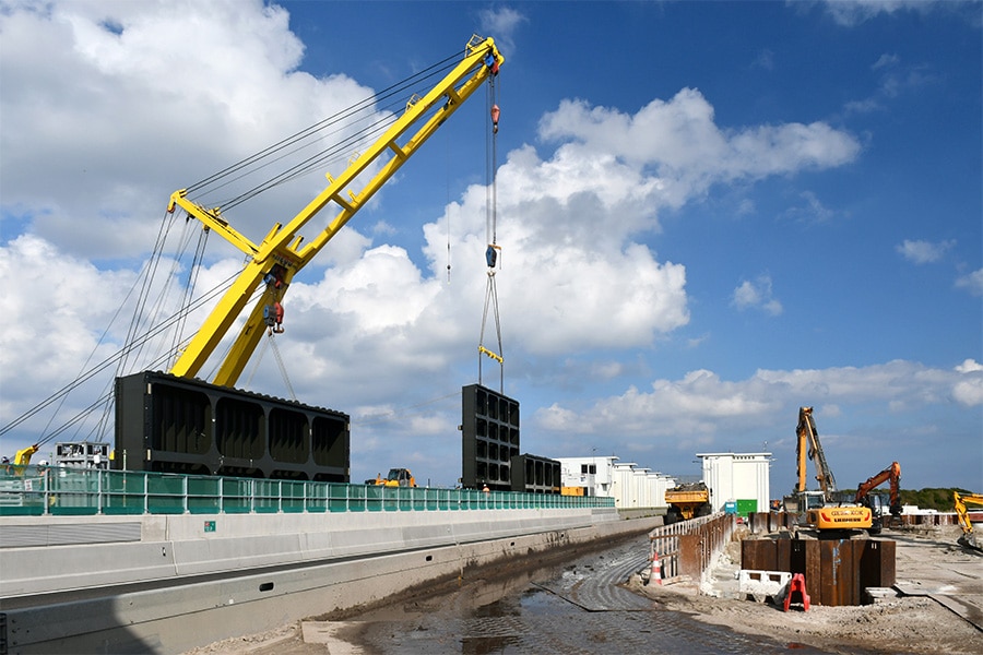
The piers were built using precast U-buckets. The U-buckets with circular recesses were placed over the tubular steel piles on welded brackets. The tubular piles were already filled with concrete and head reinforcement. After placement, a pillar reinforcement cage was installed and the U-buckets were filled with concrete. In this way, the piles, precast concrete boxes and the pillar were structurally connected. After placing the precast beams of the deck and pouring the compression layer, the deck was also structurally connected to the pillar. With this construction method, the piers could be built without a construction pit and drainage, and disruption to shipping was limited.
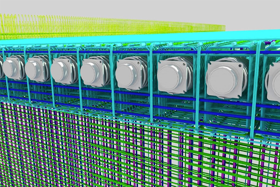
The reinforcement was modeled in its entirety in a 3D package. At the factory, the reinforcement was then assembled as much as possible in baskets and brought to the job site in its entirety. The 3D model and prefabrication gave very neat baskets that fit together well.

The design of the movable part of the bridges is essentially identical. Both bridges are electromechanically driven by a crank drive rod mechanism. A drive system connected in series was chosen. In global line this corresponds to motor gearbox 1 - intermediate shaft - gearbox 2 - crankshaft - crank arm - spring buffer - trap. By choosing a long intermediate shaft, the stiffness of the motion gear is reduced and the occurring forces are reduced.
From the point of view of minimizing maintenance, it was decided to design the steel traps as closed, boxed steel structures that are welded airtight all around. Sealing the underside leads to a reduction in the area to be preserved compared to a conventional design with an open underside. In addition, the flat finish makes the bridges easier to maintain. The bottom plates not only perform a practical function as sealing plates, but also function constructively as the bottom flange of the main girders and cross girders.
The direct-travel driving deck has a "usual" design: the deck plate thickness and welding details are in accordance with NEN-EN 1993-2. The troughs protrude through the cross girders, with the cross girder discs closely enclosing the troughs. The choice of pierced troughs allows the trough legs to be welded to the deck plate through the full length of the driving deck by an automatic welding process.
Two tail girders form the connection between the closed deck structure and the ballast box. The narrow bascule basement necessitated the use of fairly tight vertical curve radii in the lower flanges.
Louwers Mediagroep
Schatbeurderlaan 6
6002 ED Weert
 © 1987 - 2025 Louwers Media Group.