Platform on civil engineering, underground infrastructure, energy, construction equipment & construction machinery

An important connecting point and an image-defining element in the neighborhood will be the new Dock Bridge over the Dock. The new bridge will be located slightly West of the old bridge, which will be removed after the new bridge is completed.
Buro Ma.aN created the architectural design of the bridge. The shipbuilding industry, for which Vlissingen is historically known, and the nearby Schelde crane were used as sources of inspiration. Iv-Infra was commissioned by the Municipality of Vlissingen to develop this design further in technical terms, produce the DO, draw up the contract for execution and put the work out to tender. The architectural design included only the external form. To arrive at a working movable bridge, the entire structure was worked out in 3D in a computer model. In good cooperation with the architect, various changes and optimizations were made to create a working whole.

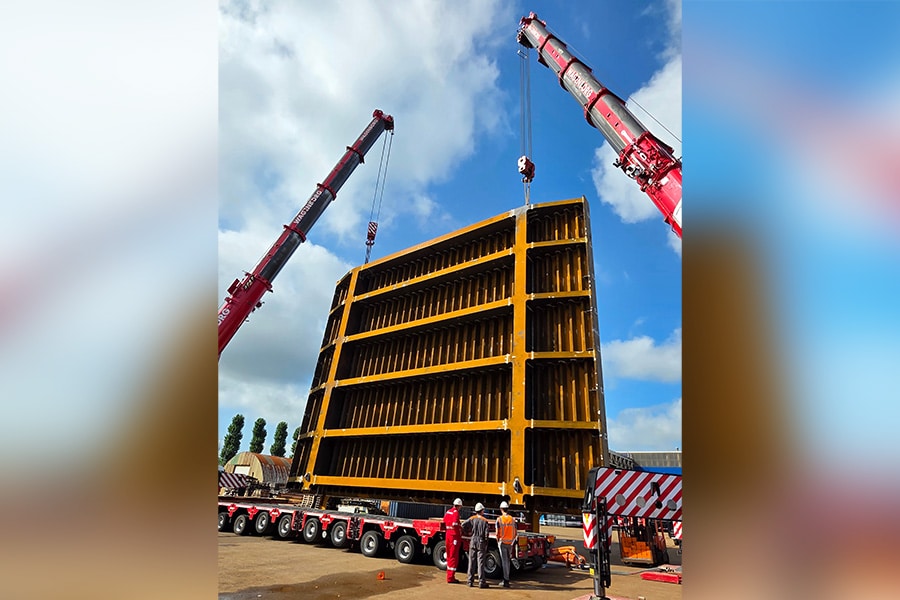
The Dock Bridge is a drawbridge that is balanced by means of two large masses in the back of the balance pins placed on top of the hameitorens. A movable bridge is generally balanced such that it is willing to close on its own with a relatively limited force on the overlay side. The bridge case weighs about 100 tons; the balance straps weigh about 45 tons each. The balance straps are reasonably balanced by themselves. Thus, in particular, the mass of the bridge halyard must be compensated with the ballast mass in the back of the balance straps. This requires about 145 tons of ballast mass, divided between the two ballast boxes. In collaboration with the architect, some modifications were made to the architectural design to make room for this mass. The balances have been extended slightly so that the mass is used more effectively. After all, the farther away from the pivot point the more effective this is. To prevent the back of the balances from touching the railing, the hameitorens have been raised by the same length. The center of gravity of the ballast box has also been lowered slightly so that the bridge will want to close of its own accord even in the open position. Thus, in the event of a failure or power outage, the bridge can still be closed.
The bridge rests on two concrete piers in the dock. Originally, the architect's idea was to house the drive and electrical installation at the bottom of the hameitorens. But those spaces, upon further elaboration, proved too small to accommodate all those components in such a way as to meet today's requirements for safety and maintainability of a movable bridge. Enlarging the hameitorens' hips would affect the bridge's appearance too much. Another solution to this is to create a basement under the bridge. The underpass height was 2m in the architectural design, exactly according to the requirements of the water board and the administrator. However, this left no room for a basement with headroom in the pillar on which the hameitorens are located. Unless a structure would be built with the floor further below the water level. However, this works out to be quite cost-prohibitive as it would require building pits. Locally, the dock is about 7m deep. Since the budget was limited, it was decided to increase the underwater height by 0.6m. This way, the slope of both approach decks does not become too steep and the design stays as close as possible to the architect's design. This created just enough space for a basement with headroom. This space can be used to place the electrical installation. There is also space for the hydraulic unit. At the same time, it is ensured that the basement can be built on the waterline without having to use a cofferdam.

The bridge is driven by two electro-hydraulic cylinders arranged at the top of the hameitorens. Several variants were examined for the bridge drive. Based on such factors as fit-in, purchase and maintenance costs, impact on the architectural image and maintainability, it was decided to place the drive in the chamber towers. These cylinders must be safely accessible for assembly, inspection and maintenance. There was just too little space available for this in the original design. Since the hamitorens were made slightly longer in order to be able to extend the balance belts, it was logical to also increase the hamitorens proportionally slightly in cross-section. This also created just enough space here for the desired accessibility of the cylinders. The cylinders push up the balance straps, causing the bridge to move. There are two access doors in both chamber towers. Behind those doors are stairs to access down into the basement and a ladder to climb up into the towers. Two levels have been created in the towers so that the bottom and top of the cylinders are accessible for inspection and maintenance.
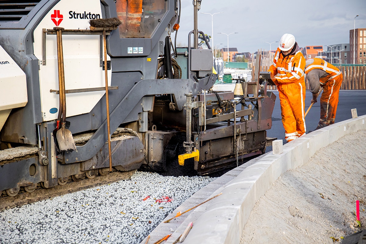
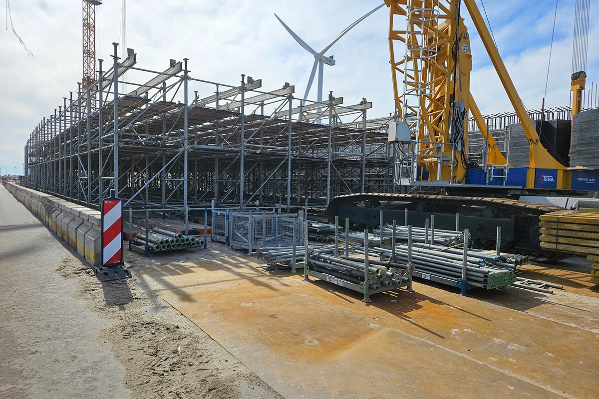
The project was tendered through public bidding based on RAW specifications and was awarded to contracting company Maas. On-site execution is in full swing. Completion is scheduled for March 2021. Iv-Infra supports Vlissingen Municipality during the execution and provides the management, daily supervision and review of the contractor's documents.