Platform on civil engineering, underground infrastructure, energy, construction equipment & construction machinery

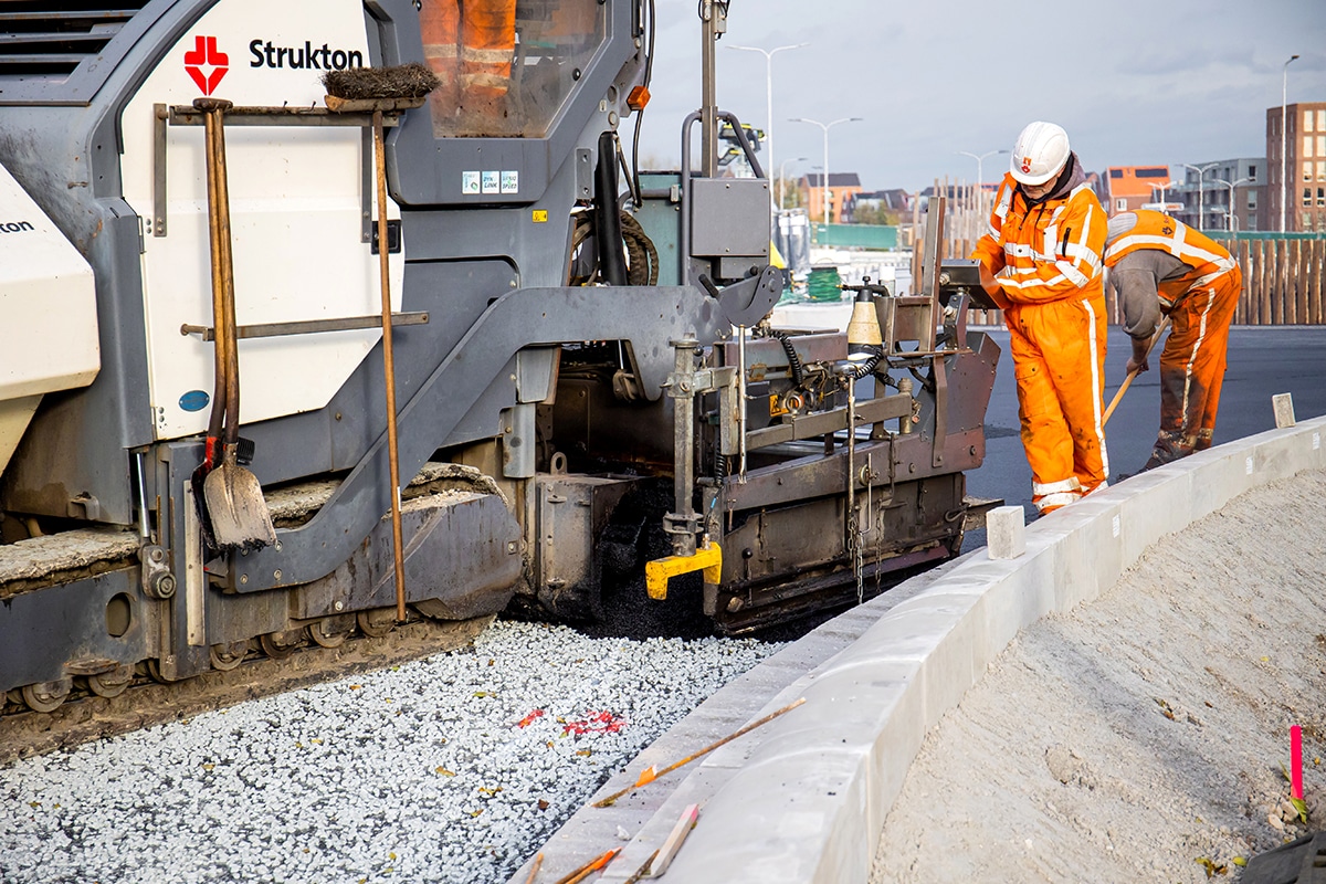
Last August, the Princess Amalia Bridge near West Knollendam was put into service. The Prinses Amaliabrug is the first of two bascule bridges to be replaced within the 'N246-N244 Trajectory Approach' project. The project involves major maintenance of the entire route between Wormerveer and Alkmaar, improving road safety and traffic flow. The province of North Holland is the client of the project.
One of the main wishes in replacing both bridges (Princess Amalia Bridge and Kogerpolder Bridge) was to minimize maintenance. In addition, the Province of North Holland stated that the alignment should not be changed. This meant that both bridges would be built in the same location as the existing bridges and the alignment of the road could not be changed. Minimizing disruption and thereby reducing and shortening on-site construction activities as much as possible was also a determining factor in the design of the bridges.
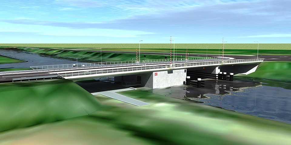
The bridges are composed of two approach bridges, a bascule basement and a steel trap. The Princess Amalia Bridge has two lanes and a separate bike path, the Kogerpolder Bridge three lanes with separate bike path. The architectural design of both bridges is similar in many areas so that both bridges clearly belong to one family in accordance with the image quality plan. By choosing a tapered bridge deck and pointed ends of piers, a slimmer appearance has been created.
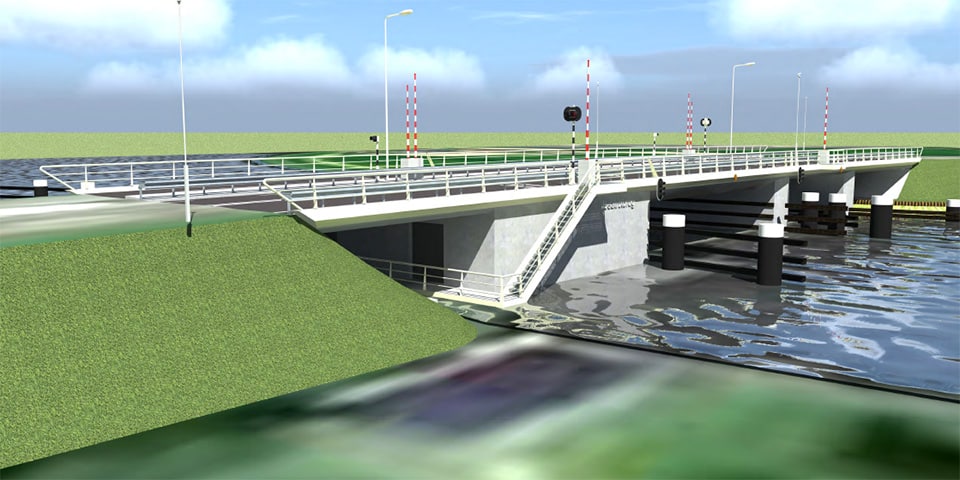
Welfare picture Princess Amalia Bridge
Welfare picture Kogerpolder bridge
The existing bridges were completely demolished. Only the existing pile foundation was not removed but remained in the ground. Because the new bridges are in exactly the same position as the existing bridges, designing the new piles was quite a puzzle. From archival records and as-built drawings, the existing pile plan was visualized. The new pile plan was designed around this and included with assumed deviations in a 3D model. This model proved to correspond very well with actual practice, so that ultimately only one pile had to be shifted during installation and this new position had to be substantiated mathematically.
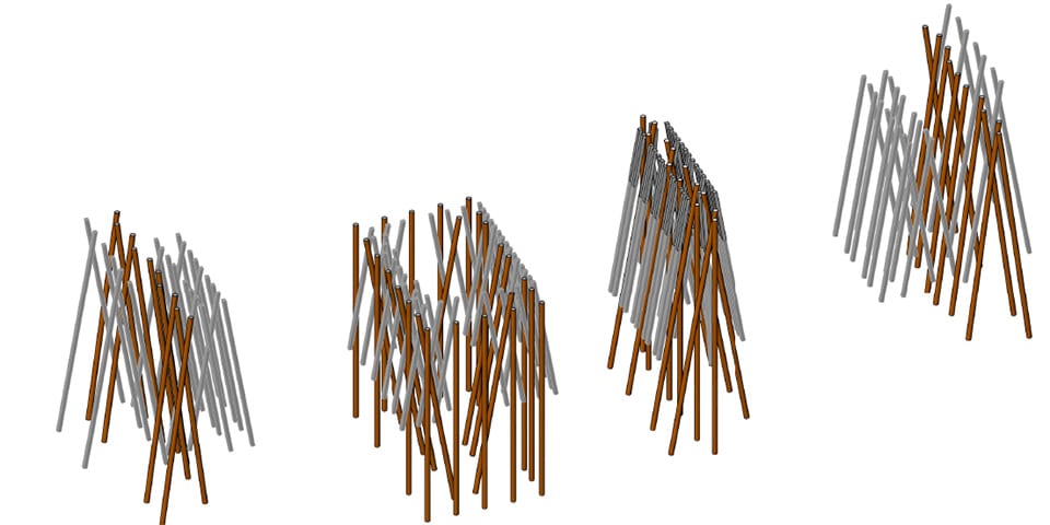
3D model showing existing piles (gray) and new piles (brown)
The starting point for the basements was a construction pit without underwater concrete. This limits the construction time. For the Princess Amalia Bridge in particular, this gives a relatively shallow basement. As a result, the counterweight has a limited arm and had to be provided with a high specific weight (steel billets). At the Kogerpolder bridge this was less of an issue because here the bridge deck is higher, this allowed the ballast box to be filled with weighted concrete.
The spans of the approach bridges to the Princess Amalia Bridge are limited, which allowed the use of solid girders. At the Kogerpolder bridge, box girders were applied. On both bridges, the decks are firmly connected to the basement and abutments (wet knot/bend-slack joints). This eliminates the need for maintenance-sensitive joint profiles.
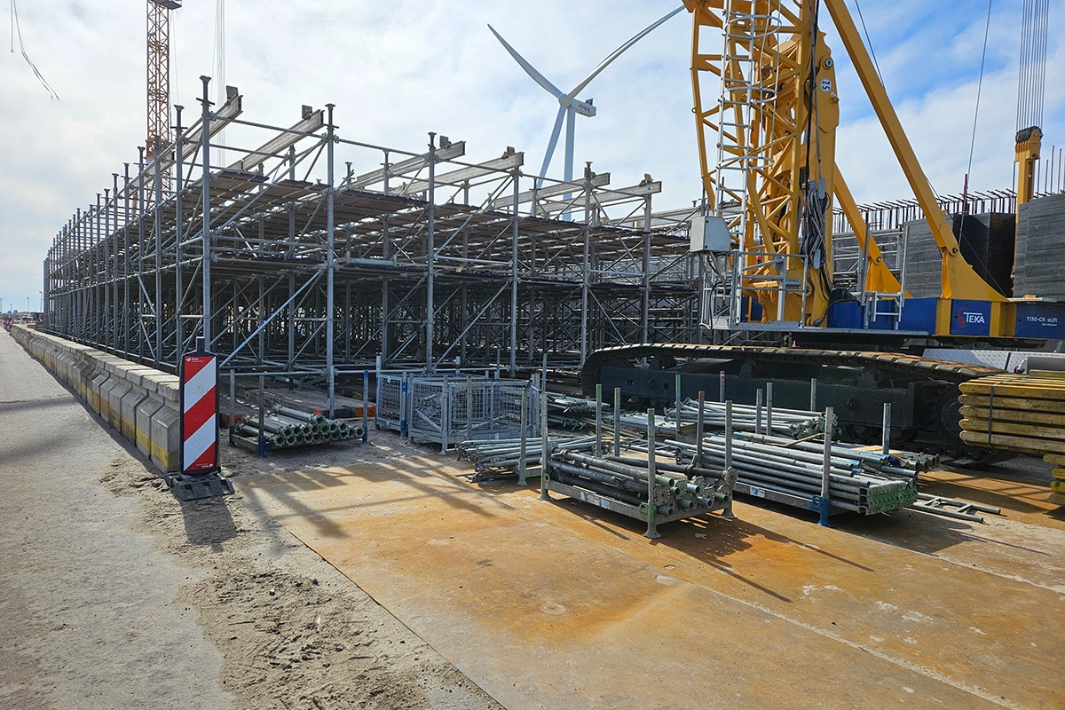
The piers were built using precast U-buckets. The U-buckets with circular recesses were placed over the tubular steel piles on welded brackets. The tubular piles were already filled with concrete and head reinforcement. After placement, a pillar reinforcement cage was installed and the U-buckets were filled with concrete. In this way, the piles, precast concrete boxes and the pillar were structurally connected. After placing the precast beams of the deck and pouring the compression layer, the deck was also structurally connected to the pillar. With this construction method, the piers could be built without a construction pit and drainage, and disruption to shipping was limited.
The reinforcement was modeled in its entirety in a 3D package. At the factory, the reinforcement was then assembled as much as possible in baskets and brought to the job site in its entirety. The 3D model and prefabrication gave very neat baskets that fit together well.
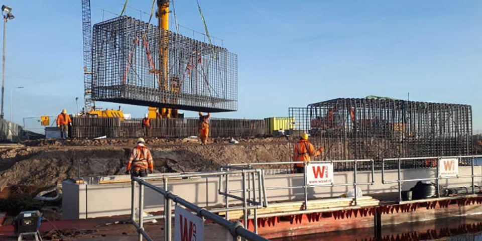
The precast reinforcement baskets of the piers are hoisted in
The design of the movable section of the Kogerpolder Bridge and that of the Princess Amalia Bridge are essentially identical.
Both bridges are electromechanically driven by a crank drive rod mechanism. A series-connected drive system was chosen. In global line this corresponds to motor gearbox 1 - intermediate shaft - gearbox 2 - crankshaft - crank arm - spring buffer - trap. By choosing a long intermediate shaft, the stiffness of the motion gear is reduced and the occurring forces are reduced.
From the point of view of minimizing maintenance, it was decided to design the steel traps as closed, boxed steel structures that are welded airtight all around. Sealing the underside leads to a reduction in the area to be preserved compared to a conventional design with an open underside. In addition, the flat finish makes the bridges easier to maintain. The bottom plates not only perform a practical function as sealing plates, but also function constructively as the bottom flange of the main girders and cross girders.
The direct-travel driving deck has a "usual" design: the deck plate thickness and welding details are in accordance with NEN-EN 1993-2. The troughs protrude through the cross girders, with the cross girder discs closely enclosing the troughs. The choice of pierced troughs allows the trough legs to be welded to the deck plate through the full length of the driving deck by an automatic welding process.
Two tail girders form the connection between the closed deck structure and the ballast box. The narrow bascule basement necessitated the use of fairly tight vertical curve radii in the lower flanges of the tail girders. The stress-increasing effects that follow from the curvature were minimized by the choice of thick and narrow flanges.
Direct force transmission from the main pivot points to the foundation piles was chosen by means of through columns between the pivot seats and the basement floor. Because of the free rotation of the trap, this is accompanied by single-sided bearing on the outside of main beams. The main pivots are interconnected by heavy coupling tube, which prevent the twisting of the tails between driving deck and ballast box.
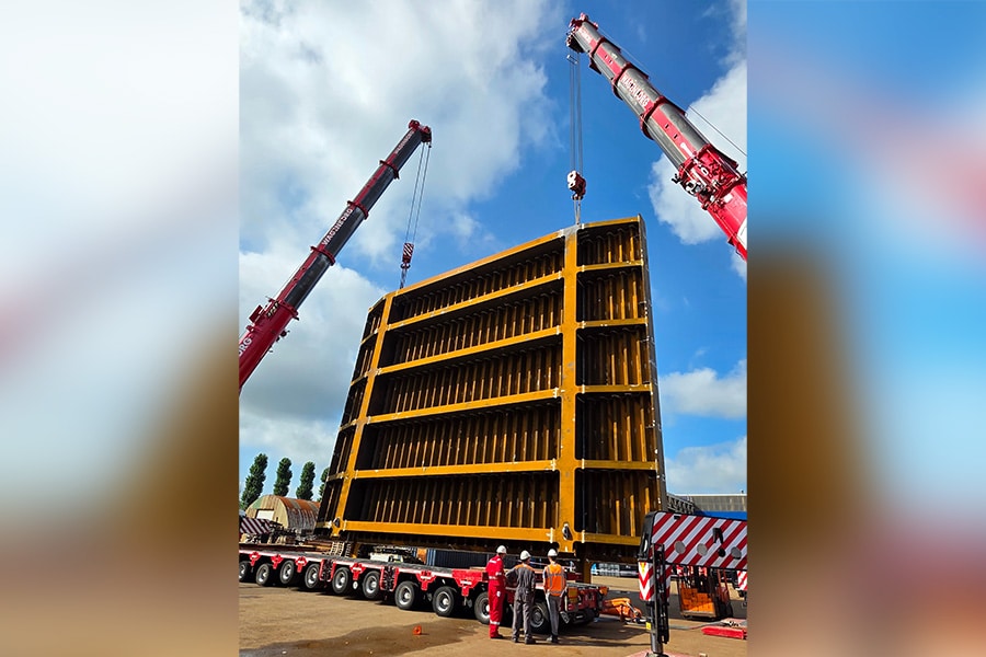
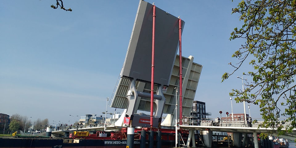
The fall of the Amaliabridge was produced in Wijhe and then, via the preserver in Amsterdam, transported across the Zaan to its final location. During the last part of the transport, a number of narrow bridges and locks had to be passed, so the halyard was transported on the pontoon at an angle for the last few kilometers.
The trap was jacked in horizontally. To jack the bridge into the main waterway from a pontoon, temporary ballast was applied to the forebay and the ballast box was filled only after placement. Construction time was minimized by packing the steel ballast billets into crates, which were lifted from the approach bridge into the ballast box. The trap was then fixed in the open position on the securing device (to allow free passage for shipping traffic) and work was carried out on the basement fittings and basement roof. The Princess Amalia Bridge was commissioned on August 10, 2019.
The Kogerpolder Bridge is currently under heavy construction. This bridge is expected to be completed in early 2020.
| Princess Amalia Bridge | Kogerpolder Bridge | |
| Bridge length | 71,2 m | 87,7m |
| Bridge width | 15,4 m | 21,4 m |
| Free passage width | 16,5 m | 15,5 m |
| Trap length (including ballast box) | 27,0 m | 26,7 m |
| Main span length | 19,8 m | 18,8 m |
| Construction height (approx.) | 1200 mm | 1300 mm |
| Mass drop (excluding ballast) | 238 t | 331 t |
| Ballast weight | 205 t | 227 t |
| Design life | 100 years | 100 years |
| Traffic class | 2 (medium distance) | 2 (medium distance) |
| Number of lanes | 2 | 3 |
| Consequence class | CC3 | CC3 |