Platform on civil engineering, underground infrastructure, energy, construction equipment & construction machinery

The concept of the self-closing float valve® at the dyke reinforcement Steyl - Maashoek seems so simple: a concrete tank that fills up with water so that the floating element with steel valve moves up autonomously and protects the monastery village of Steyl from high water. Practice proved more difficult, given the limited space, present foundations of the existing retaining wall, complicating cables and pipes in the subsurface, and much more. Dijkzone Alliance engaged engineering firm Maters and De Koning for the structural design of the civil supporting structures.
Maters en De Koning is familiar with the Limburg landscape and has previously been involved in the area development Ooijen-Wanssum, also for Dura Vermeer. "Dijkversterking Steyl - Maashoek is very similar to that project in terms of roles," knows Maikel Bal, project manager at Maters and De Koning. "We are responsible for the engineering and modeling of the civil part of the self-closing Float Barrier®, a huge concrete container 130 meters long, internally 2.5 meters wide and 4 meters high, which will be founded on piles and a sheet pile wall. We are also an important link between the execution, the geotechnical engineering that Fugro is largely responsible for, and Hollandia Infra's steel flap."
The flotation element with the water retaining steel valve creates quite a force play on the concrete box structure in high water situations. "The principle has not been applied on this scale before," says Idde-Jan Terpstra, senior structural engineer at Maters and De Koning. "There are strict requirements for deformation and watertightness. Virtually no (leakage) water is allowed to seep through or too much seepage water underneath. The latter now does happen with the existing retaining wall, which is founded on bored piles, so there is a risk of piping. That is why the new situation uses a sheet pile wall, which has a dual function: to transfer the forces in the subsurface and at the same time act as a seepage and piping screen."
Meeting deformation requirements is challenging, according to the gentlemen. This is because an old clay channel runs right through the barrier. "This unbearable layer locally causes much greater deformation than at the ends of the long trough where the gate structures also provide additional stiffness because of the angled bearings," says Maikel. Idde-Jan adds: "In addition, we have to deal with a borehole-free zone, the Venloschol (a water-sealing layer to protect drinking water supplies in Limburg, ed.), which gave a lot of challenge in the design due to the limited allowable input level of the foundation elements. It was up to us to include the province in our design and present our arguments for dealing with this in a safe way. Again supported in this with analyses from Fugro."
The unique constraints of the project had repercussions on the design of the foundation. This meant that the obvious knobs you can normally turn, such as setting piles deeper or using shoring piles or anchoring to absorb horizontal forces, were not possible or were limited. This made it necessary to use advanced 2D Plaxis models to have Fugro analyze the interaction between piles, sheet piling and the adjacent slope.
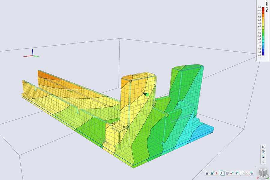
Maters en De Koning then calculated the entire trough structure in SCIA Engineer, fed by the Plaxis results from Fugro. As a result, uncertainties due to the complex behavior of the varying soil structure as well as the forces of Hollandia Infra's steel valve on the concrete bucket were brought into focus, and a structure was designed that could withstand high water for at least 100 years. "Such coordination with, among other things, two different calculation programs makes the project unique from a mathematical point of view alone," Maikel believes.
Frans Moen, BIM modeler at Maters and De Koning adds: "We made good arrangements beforehand and agreed on a fixed point to build the model, so that we could quickly import Hollandia Infra's Inventor model into our Revit model. The same goes for the AutoCAD drawings from the landscape architect and the cable and piping work provided by the alliance."
As if there were not enough interfaces, a pressurized sewer is also being relocated in the immediate vicinity of the newly constructed barrier. "The possible consequences of the sewer collapsing, leading to a huge erosion crater, were visualized. Then the consequences for the basin construction and foundation were mapped in our 3D model. For this and all other load cases, we created a model of the valve at each water level, demonstrating that the barrier functions safely at each water level. And so we are an important link in a lot of different parts. A role we are happy to take on."